-
Products
- Application
- Company
-
Services
- Resources
- News
-
Contact Us

The N76E003 is an embedded flash type, 8-bit high performance 1T 8051-based microcontroller. The instruction set is fully compatible with the standard 80C51 and performance enhanced.
The N76E003 contains a up to 18K Bytes of main Flash called APROM, in which the contents of User Code resides. The N76E003 Flash supports In-Application-Programming (IAP) function, which enables on-chip firmware updates. IAP also makes it possible to configure any block of User Code array to be used as non- volatile data storage, which is written by IAP and read by IAP or MOVC instruction. There is an additional Flash called LDROM, in which the Boot Code normally resides for carrying out In-System-Programming (ISP). The LDROM size is configurable with a maximum of 4K Bytes. To facilitate programming and verification, the Flash allows to be programmed and read electronically by parallel Writer or In-Circuit-Programming (ICP). Once the code is confirmed, user can lock the code for security.
The N76E003 provides rich peripherals including 256 Bytes of SRAM, 768 Bytes of auxiliary RAM (XRAM), Up to 18 general purpose I/O, two 16-bit Timers/Counters 0/1, one 16-bit Timer2 with three-channel input capture module, one Watchdog Timer (WDT), one Self Wake-up Timer (WKT), one 16-bit auto-reload Timer3 for general purpose or baud rate generator, two UARTs with frame error detection and automatic address recognition, one SPI, one I C, five enhanced PWM output channels, eight-channel shared pin interrupt for all I/O, and one 12-bit ADC. The peripherals are equipped with 18 sources with 4-level-priority interrupts capability.
The N76E003 is equipped with three clock sources and supports switching on-the-fly via software. The three clock sources include external clock input, 10 kHz internal oscillator, and one 16 MHz internal precise oscillator that is factory trimmed to ±1% at room temperature. The N76E003 provides additional power monitoring detection such as power-on reset and 4-level brown-out detection, which stabilizes the power-on/off sequence for a high reliability system design.
The N76E003 microcontroller operation consumes a very low power with two economic power modes to reduce power consumption- Idle and Power-down mode, which are software selectable. Idle mode turns off the CPU clock but allows continuing peripheral operation. Power-down mode stops the whole system clock for minimum power consumption. The system clock of the N76E003 can also be slowed down by software clock divider, which allows for a flexibility between execution performance and power consumption.
With high performance CPU core and rich well-designed peripherals, the N76E003 benefits to meet a general purpose, home appliances, or motor control system accomplishment.
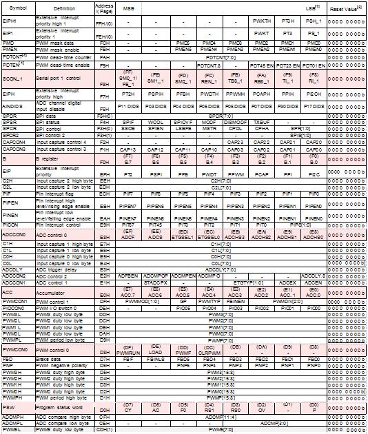
| SFR Page | Addr | 0/8 | January 9th | 2/A | 3/B | 4/C | 5/D | 6/E | 7/F |
| 0 | F8 | SCON_1 | PDTEN | PDTCNT | PMEN | PMD | PORDIS | EIP1 | EIPH1 |
| 1 | - | - | - | ||||||
| 0 | F0 | B | CAPCON3 | CAPCON4 | SPCR | SPSR | SPDR | AINDIDS | EIPH |
| 1 | SPCR2 | - | - | - | |||||
| 0 | E8 | ADCCON0 | PICON | PINEN | PIPEN | PIF | C2L | C2H | EIP |
| 1 | - | ||||||||
| 0 | E0 | ACC | ADCCON1 | ADCCON2 | ADCDLY | C0L | C0H | C1L | C1H |
| 1 | |||||||||
| 0 | D8 | PWMCON0 | PWMPL | PWM0L | PWM1L | PWM2L | PWM3L | PIOCON0 | PWMCON1 |
| 1 | |||||||||
| 0 | D0 | PSW | PWMPH | PWM0H | PWM1H | PWM2H | PWM3H | PNP | FBD |
| 1 | |||||||||
| 0 | C8 | T2CON | T2MOD | RCMP2L | RCMP2H | TL2 PWM4L | TH2 PWM5L | ADCMPL | ADCMPH |
| 1 | |||||||||
| 0 | C0 | I2CON | I2ADDR | ADCRL | ADCRH | T3CON PWM4H | RL3 PWM5H | RH3 PIOCON1 | TA |
| 1 | |||||||||
| 0 | B8 | IP | SADEN | SADEN_1 | SADDR_1 | I2DAT | I2STAT | I2CLK | I2TOC |
| 1 | |||||||||
| 0 | B0 | P3 | P0M1 | P0M2 | P1M1 | P1M2 | P2S | - | IPH PWMINTC |
| 1 | P0S | P0SR | P1S | P1SR | |||||
| 0 | A8 | IE | SADDR | WDCON | BODCON1 | P3M1 | P3M2 | IAPFD | IAPCN |
| 1 | P3S | P3SR | |||||||
| 0 | A0 | P2 | - | AUXR1 | BODCON0 | IAPTRG | IAPUEN | IAPAL | IAPAH |
| 1 | |||||||||
| 0 | 98 | SCON | SBUF | SBUF_1 | EIE | EIE1 | - | - | CHPCON |
| 1 | |||||||||
| 0 | 90 | P1 | SFRS | CAPCON0 | CAPCON1 | CAPCON2 | CKDIV | CKSWT | CKEN |
| 1 | |||||||||
| 0 | 88 | TCON | TMOD | TL0 | TL1 | TH0 | TH1 | CKCON | WKCON |
| 1 | |||||||||
| 0 | 80 | P0 | SP | DPL | DPH | RCTRIM0 | RCTRIM1 | RWK | PCON |
| 1 |


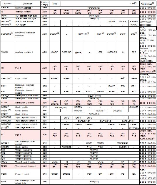
| Symbol | Definition | Address / (Page) | MSB | LSB[1] | Reset Value[2] | ||||||||
| RCTRIM1 | Internal RC trim value low byte | 85H | - | - | - | - | - | - | - | HIRCTRIM[0] | 0 0 0 0 0 0 0 0 b | ||
| RCTRIM0 | Internal RC trim value high byte | 84H | HIRCTRIM[8:1] | 0 0 0 0 0 0 0 0 b | |||||||||
| DPH | Data pointer high byte | 83H | DPTR[15:8] | 0 0 0 0 0 0 0 0 b | |||||||||
| DPL | Data pointer low byte | 82H | DPTR[7:0] | 0 0 0 0 0 0 0 0 b | |||||||||
| SP | Stack pointer | 81H | SP[7:0] | 0 0 0 0 0 1 1 1 b | |||||||||
| -87 | -86 | -85 | -84 | -83 | -82 | -81 | -80 | Output latch, | |||||
| P0 | Port 0 | 80H | P0.7 | P0.6 | P0.5 | P0.4 | P0.3 | P0.2 | P0. 1 | P0.0 | 1 1 1 1 1 1 1 1 b | ||
| Input, | |||||||||||||
| XXXX XXXXb[3] | |||||||||||||
